How To Plank The Hull of a Bluff Bow Model Ship
- Updated on:
- Written by Gary Renshaw
Learn How To Plank The Hull of a Bluff Bowed Wooden Model Ship with this Comprehensive 40-Step Build Guide From Modelers Central.
The hull is the single largest part of a model ship. Building the hull correctly will determine the final shape and appearance of the model. In your kit, you will find a number of plywood sheets with laser-cut parts. Use the kit’s plans and instructions to identify and number each part on the plywood sheets with a pencil. Do this before removing any parts from the plywood sheet.
1. Constructing the Hull
To construct the hull follow these steps.
Step 1
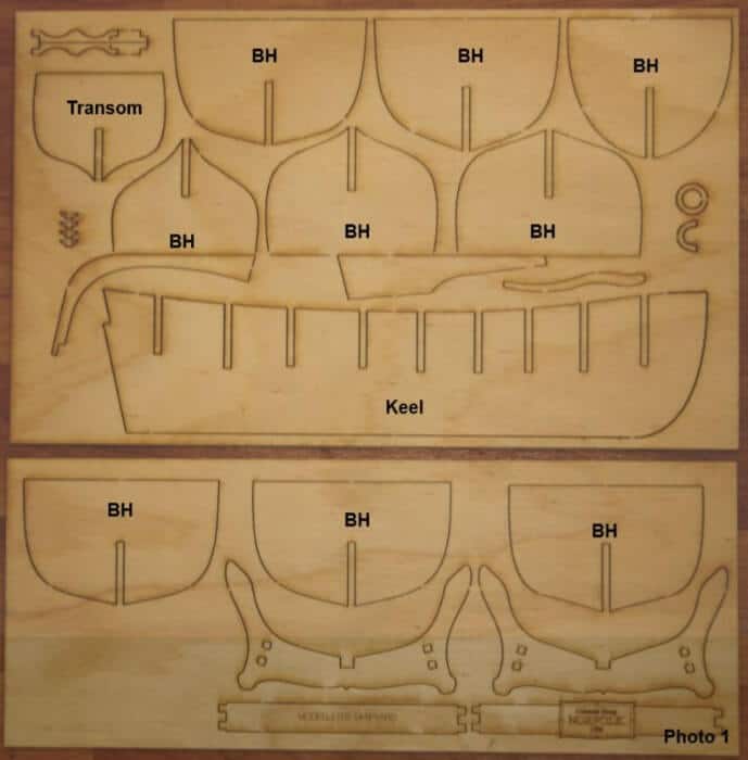
In the kit there will be a 4mm thick plywood sheet as shown Photo 1 below. On this sheet there will be a number of parts for the model. The keel, bulkheads and transom are the parts needed to construct the hull. When fitted and glued together these parts form the skeleton of the hull. The keel, bulkheads (BH) and transom are identified in Photo 1.
The keel is the ship’s main structural piece. It runs longitudinally down the centre of the model from the stem (or bow) – front—to the stern—the rear—of the model. The keel is the centre piece of the model and everything is built from it.
The bulkheads are fixed at right angles to the keel and provide strength to the hull. Throughout this course we will refer to the bulkheads as bulkhead frames.
The transom is fixed at right angles to the keel and sits at the stern. The transom is not a bulkhead but does form part of the hull construction.
Step 2
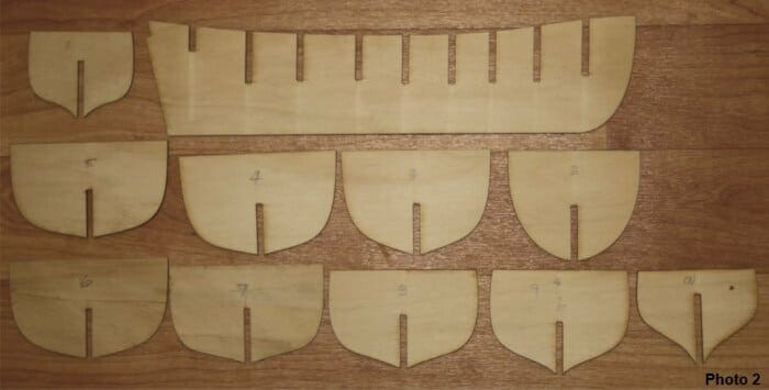
Remove the keel, bulkhead frames and transom from the 4mm plywood sheet. Use a snap blade knife to carefully cut through the tabs holding the parts to the main sheet.
Step 3
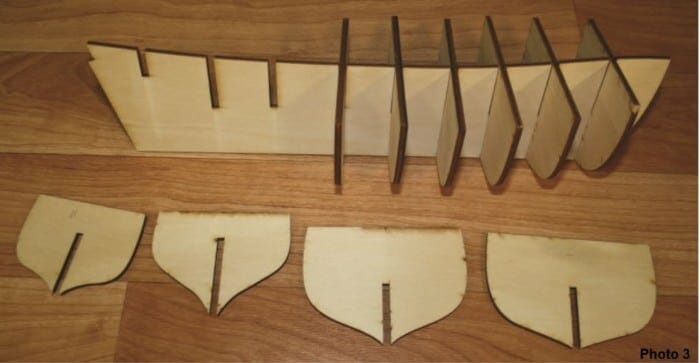
Dry fit the bulkhead frames into the keel slots. Do not glue anything at this stage. Do not force the bulkhead frame into the keel slot. You may need to use a flat needle file to fractionally open the slot in both the keel and bulkhead frame. The fit should be firm but no loose.
There may be a need to adjust the slot depth in the keel and/or bulkhead frames to ensure the top edge of each bulkhead frame is flush with the top edge of the keel. Do not glue anything at this stage.
Step 4
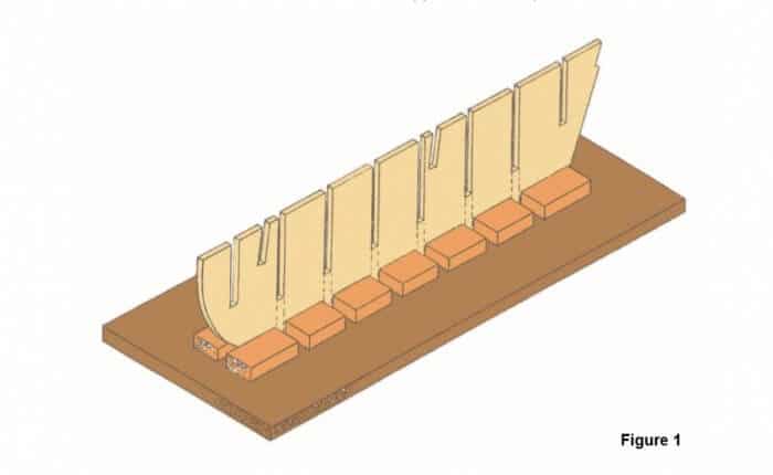
For larger models it is wise to make a working base as shown Figure 1. This will help to ensure the keel does not become distorted. Cut the slots in the keel supports to correspond with the bulkhead frames.
Step 5
It is very important to ensure the bulkhead frames are fitted and fixed square to keel. Use “bull dog” clips placed on the keel and up against the bulkhead frame to hold the bulkhead square while the glue sets.
Step 6
The next step is to fit any bow blocks and stern blocks if the model has them.
The stern blocks are fitted and glued in place on either side of the keel at the stern between the last bulkhead frame and the transom. These blocks are used to provide a larger surface area on which to fix the planks at the stern and give added strength to the stern area. Fit them at this point if your model has stern blocks.
The bow blocks are fitted and glued in place on either side of the keel at the bow and in front of the first bulkhead frame. These blocks will provide a larger surface area on which to fix the planks at the bow.
For a bluff bowed hull the planks will have to be shaped and bent in some cases at right angles. The large bow blocks are particularly important as they provide a greater surface area on which you can glue the planks thus allowing for greater strength.
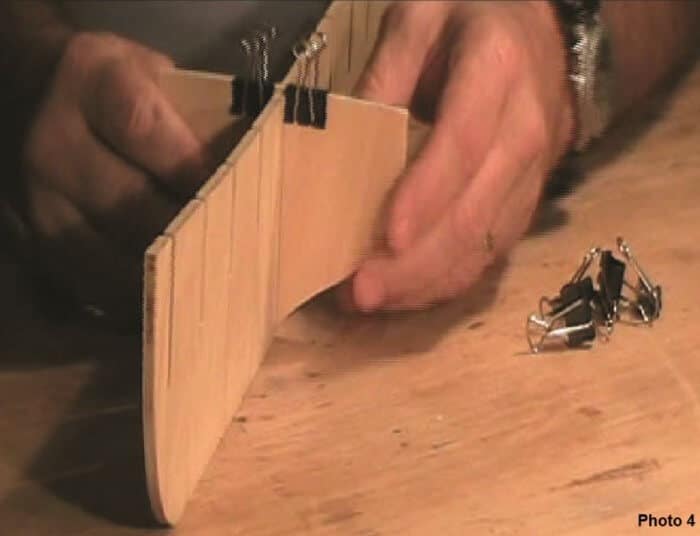
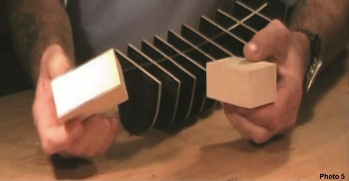
In a kit that has a bluff bow, the manufacturer will provide blocks of wood that will need to be shaped to fit between the first bulkhead frame on both sides of the keel at the bow—Photo 5. Sometimes a series of 4mm plywood pieces are provided that will be used to build up the equivalent of a bow block once glued in place together.
Irrespective of which method is used to create the bow blocks you will need to shape the blocks.
Follow the next steps to achieve the correct shape of the bow blocks.
Step 7
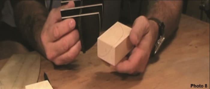
To shape the bow blocks first trace the outline of the first bulkhead frame on to one bow block
Next place the false deck on the top of the bulkhead frames and align it with the front of the keel. Place the bow block in place and trace on to the block the curvature of the false deck at the bow—
You will now have two curves on the bow block. You will need to shape the block to these two lines.
Step 8
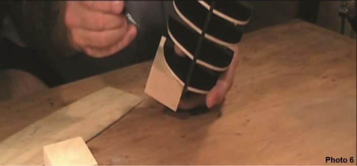
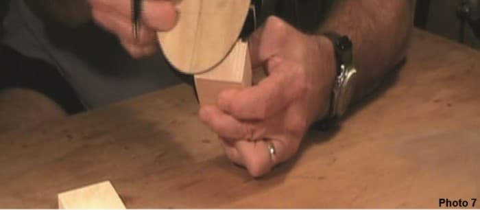
To shape the bow blocks you can use a range of hand or power tools. A band saw can be used to remove most of the unwanted timber. A rasp can also be used for this purpose.
Once most of the unwanted timber has been removed use files and sandpaper to achieve the final finish.
As you progress continually check the shape of the block against the keel and first bulkhead frame for accuracy.
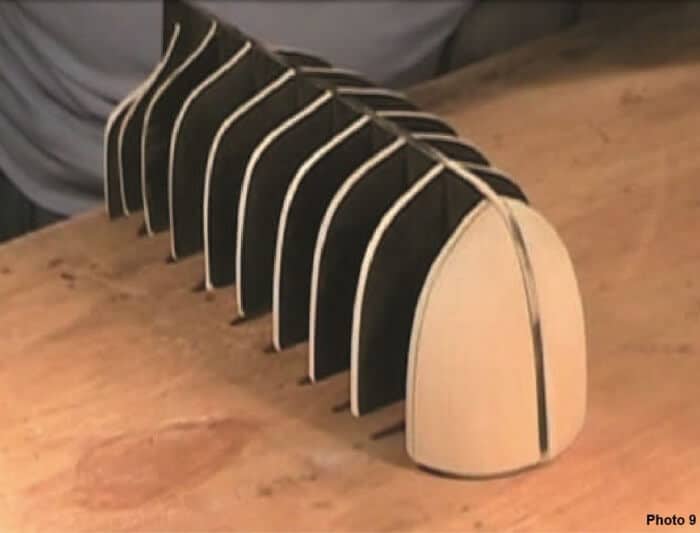
Once you are satisfied with the shape achieved use a two part epoxy glue to fix the bow blocks in place—Photo 9.
Step 9
The next step is to fit and fix the false deck to the hull skeleton. The false deck is part of the 2mm plywood sheet. Fitting the false deck at this stage will provide added strength to the whole hull structure.
On some models the false deck is fitted later.
Step 10
After the bulkhead frames have all been squared to the keel and glued in place and the glue has set it is now time to prepare the bulkhead frames for planking.
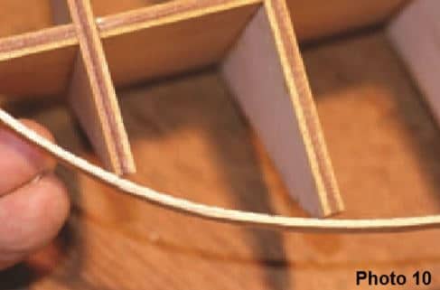
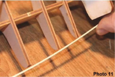
Take one of the first layer planks that will be used and lay it across the bulkhead frames. You will see that at the bow the plank does not touch the full face of the bulkhead frame—see Photo 10. The same is the case at the stern—see Photo 11. Across the mid-ship bulkhead frames the plank will lay flat on the bulkhead frames.
Step 11
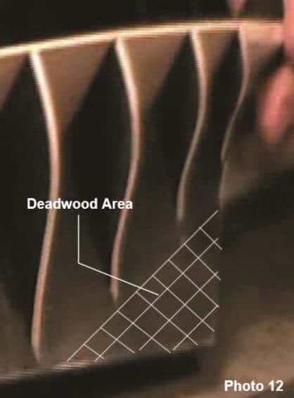
The next step to consider is the keel at the stern. Pay particular attention to this area. The total thickness of this area must be such that when planked with all layers of planking it is the same thickness at the stern post and rudder. Deadwood Area The area between the bottom edge of the keel and the bottom of the bulkhead frames at the stern is known as the deadwood area—See Photo 12.
Depending upon the type of ship that is being modelled the deadwood area may be small or large.
The deadwood area will be planked with two layers of planking consistent with the rest of the hull.
The stern post and rudder however will only be planked with the second layer of planking. So when the stern post and rudder are eventually fitted there is the need to ensure there is a consistent thickness between stern post, rudder and the stern area of the keel.
For example the keel, stern post & rudder will all be taken from the 4mm plywood sheet.
The stern post and rudder will be planked with the second layer of planking —say 0.6mm walnut. However the keel will be planked with the first layer of planking—say 2mm thick (on each side) and then planked with the second layer of planking. Clearly when the stern post and rudder are fitted there will be a significant discrepancy between the thickness of the stern area of the keel and the stern post and rudder. To ensure there is consistency of thickness between the stern post, rudder and the hull in this area there is the need to ensure that when the first layer of planking is fixed in place the total thickness does not exceed the thickness of the stern post/rudder post.
To achieve this you will need to take two steps.
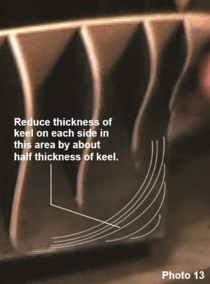
Step 1. Before fitting the first layer of planking reduce the thickness of the keel in the area by approximately 1mm on each side—reduce the keel thickness by about half.
Step 2. Once the first layer of planking has been fitted then reduce the thickness of this planking by approximately 1mm on each side as well—fractionally adjusting to meet required thickness.
This will then reduce the total thickness of the keel and first layer of planking in the area to be 4mm thick and thus meeting the requirement for consistency of thickness so that when the second layer of planking is fitted there will be consistency of thickness between the keel and the stern post and rudder.
2. Planking the Hull
We will now be completing the first layer of planking of a bluff bowed hull. The approach will be applicable to all bluff bowed wooden model ships with a plank on bulkhead frame construction.
There are many approaches to planking the hull of a wooden model ship. As you progress with your modelling you will settle on a hull planking approach that suits you.
Planking the hull is not technically difficult but it does require some thought and study so that the principles are understood. It also requires some patience. Once mastered the process is straight forward.
There are a few points to remember:
- Use a mini plane to taper the planks.
- Always taper the lower edge of the plank—ie the edge that will be closer to the keel.
- Prepare two planks together—one for each side of the hull. It is most important to fit and glue the planks in pairs—one on each side of the hull as this will minimise the chance of the keel being distorted or bent.
Planking First Principles
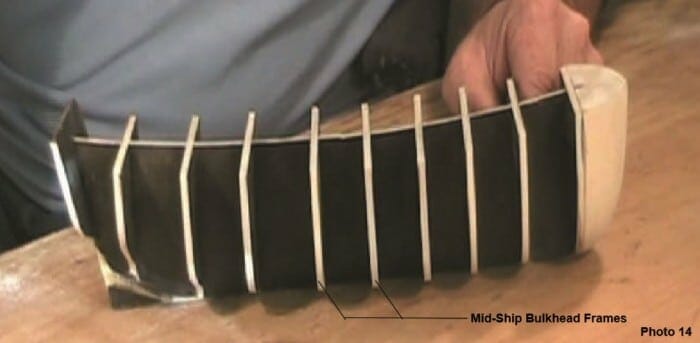
On the model you are building spend a few moments with a dressmakers tape measure and measure from the top of the each bulkhead frame around the outside of the frame to the toe of the bulkhead frame where it meets the keel. You will notice that the measurements around the bulkhead frames in the middle or “mid-ship” of the model are greater than the measurement around the bulkhead frames at the bow (front) of the model.
We always assume that the “mid-ship” bulkhead frames are the largest distance and it is at this part of the model the planks will be at their full width. From your measurements it will be clear that if you are to fit one plank along the full length of the hull you will need to taper the planks that fit across the bulkhead frames at the bow of the model. We will now consider this further with a few examples.
Mid-Ship Bulkhead Frames
It is assumed that the planks laid across the mid-ship bulkhead frames are at their maximum width. We need to determine how many planks will fit into the area between the top of these bulkhead frames and the keel.
As an example let’s say the measurement from the top of the mid-ship bulkhead frames 4 & 5 to the keel is 120mm.
Question: If the width of the planks we are using is 5mm then how many planks will fit across the midship bulkhead frames to cover it completely?
Answer: If the measurement is 120mm and the width of the planks to be used is 5mm then divide 120mm by 5mm that is 120/5 = 24 planks will be needed to fit into the area. These planks laid across the mid-ship frames will not be tapered or reduced in width across these bulkhead frames.
Fore Bulkhead Frames
Now let’s say the measurement from the top of the bulkhead frame 2 to the keel is 80mm. As 24 planks will have to fit into this area then the plank width at bulkhead frame 2 will need to be reduced. The question is what will the width of each plank have to be to fit 24 planks into this area?
Question: What is the plank width needed at bulkhead frame 2 if 24 planks have to fit into the area?
Answer: If the measurement is 80mm—then divide 80mm by 24 planks that is 80/24 = 3.33mm. So the plank wide at bulkhead frame 2 needs to be 3.33mm to ensure that 24 planks will fit into this area.
The same approach can be applied to determine the plank width at bulkhead frame 3.
Stern Bulkhead Frames
You will recall that the area between the bottom edge of the keel and the bottom of the bulkhead frames at the stern is known as the deadwood area.
When making your measurements of these stern bulkhead frames include the “deadwood” in your measurement.
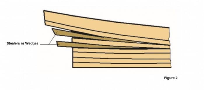
Across these bulkhead frames you will find the measurement from the top of the bulkhead frame to the bottom of the keel will be greater than it is at the “mid-ships” bulkhead frames. Where this occurs you will be inserting short triangular planks known as “Stealers” or “Wedges” to cover the extra distance. The use of stealers or wedges will be dealt with later.
3. Fitting the First Plank
The placement of the very first plank (plank 1) is most important. Determine from the plans and/or the written kit instructions the position of the first plank(s). In “real” shipbuilding it was usual to start planking at the keel and work upwards. However in model ship building we usually start the first plank in one of three positions:
1. With a ship which has a “flush” or straight upper deck, such as “Bounty” or “Port Jackson” then the first plank is laid with its upper edge level with the deck surface. In some cases the first plank will have its top edge 5mm to 10mm below the deck level. This is done to facilitate the con struction of bulwarks at a later stage but in any case it will be parallel to the line of the deck.
2. In the case of those models in which the “upper” or “weather” deck is in either two or three distinct sections, at differing levels, then the first plank is commonly run along the line of the “middle” or “main” deck then follows its natural course both “fore” and “aft”.
3. Many models that feature below deck open gunports, will require the first plank to follow the line of the gunports and it will run immediately above or below a row of gunports.
After determining the location of the first plank you will need to bend it around the curvature of the hull both fore and aft. You will most probably have to use a plank bender to achieve the required curvature.
Take one of the planks to be used and place it in position. Gently spring the plank around the bow. At the point where the plank starts to bend—mark this as point A—Photo 15.
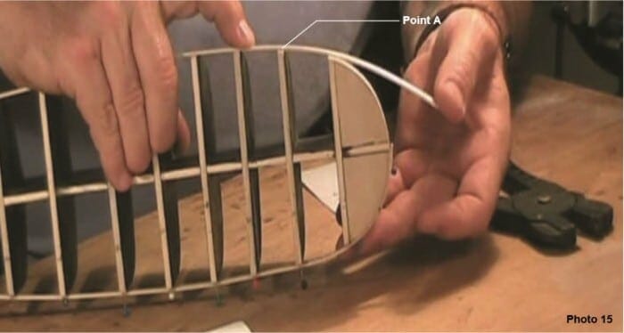
We are going to be very systematic in our preparation for planking.
Take a second plank and transfer this point on to it. On each plank mark an arrow pointing towards the bow. Also mark each plank “P” for port (left) and “S” for starboard (right). We will do this for all the planks we prepare. We will also make all planks in pairs.
The first plank will NOT be tapered.
From Point A use a hand held plank bender to gently crimp the plank toward the bow—Photo 16. Trial fit the plank. If needed use the plank bender again by gently crimping between the previous crimps. This will increase the curvature of the plank. Repeat this process until you are satisfied with the curvature of the plank.
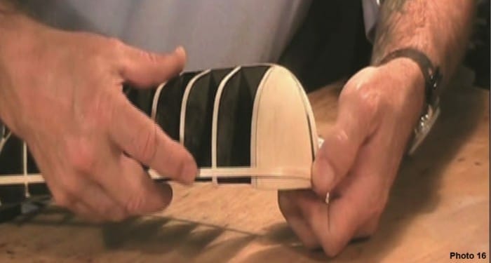
Now that you have shaped the first plank it is now time to fit and fix it in position. Note again that the first plank will not be tapered.
Use PVA glue to fix the first plank in position. Make sure that both planks (left and right or “port” and “starboard”) follow the same line and are a mirror image of each other. In large bluff bowed models the first two, three or four planks fitted are not tapered.
For the Norfolk, the first plank is glued in and placed 3.5mm below the top of each bulkhead frame. This is done to allow a bulwark to be fitted later.
It is important to check that the first planks are symmetrical—check that they are a mirror image of each other at the bow and the stern.
We will now turn to calculate the plank width at each bulkhead frame so that we can complete the first layer of planking.
4. Completing the First layer of Planking
For the model you are building establish a table as shown below representing the number of bulkhead frames—include the transom.
To determine the plank width at each bulkhead frame use a dressmakers tape measure to measure the distance between Plank 1 and the keel at each bulkhead frame. Record these measurements in your table— see Table 1 below which is for the Norfolk.
For the Norfolk the distance between Plank 1 & the keel at the mid-ship bulkhead frames is 88mm. The plank width is 5mm. Therefore there will need to be 88/5 = 17.6 planks to be fitted to cover the hull. We will approximate this figure to 17 planks as there will always be a small amount to creep in plank width as you progress down the hull.
For the model you are building apply the above approach to determine the number of planks required. Then, using the measurements you have made and recorded in the table, divide each by the number of planks to determine the plank width at each bulkhead frame. Record in your Table.

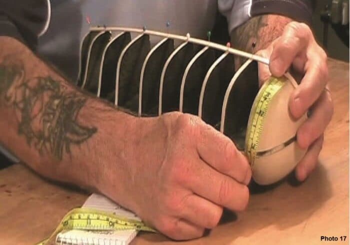
From the measurements for the Norfolk you will find that approximately 1mm will need to be tapered off the bow and stern end of the planks. This is typical for a bluff bowed hull.
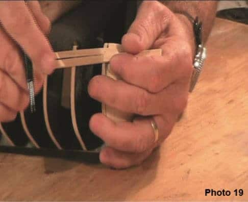
Again for the Norfolk you will find the planks will need to be tapered from Point A (where the plank starts to bend around the bow) previously identified—Photos 18 & 19
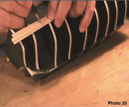
At the stern the planks will need to be tapered from approximately half way between bulkhead frames 8 & 9—Photo 20. Clearly mark each of these points on your planks—always prepare two planks together.
Don’t forget to mark your planks as previously described.
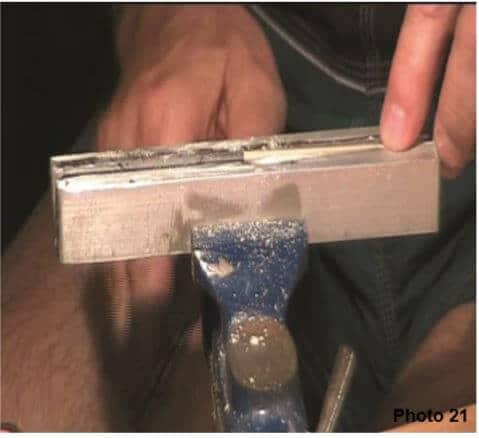
Taper the two planks together. To taper the planks place them in a vice with the amount to be taken off sitting proud of the vice jaws and position the marked point sitting flush with the jaws—Photo 21. Use a mini plane and/or file to remove the unwanted timber.
Use this approach for all the planks to be prepared.
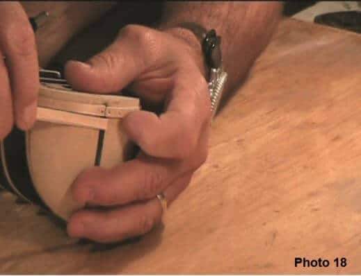
Fit each plank under the previously placed plank. Glue and pin in position.
The next point is most important: As you progress with you planking down the hull you will arrive at a point where the plank does not want to lay flat. Forcing the plank into position will cause it to twist and a gap will appear between the plank and the bow block.
At this point you will have to change the direction of the plank to ensure it sits flat on the hull. Follow the steps below to achieve this change in plank direction.
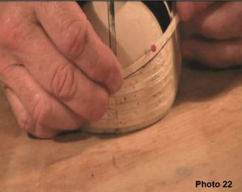
1. Lay the plank along the length of the hull against the previously placed plank. At the bow you will see the plank wants to take a different direction—allow the plank to follow its natural course and lay over the previously placed plank—Photo 22. Temporarily pin the new plank in position and use a pencil to mark the line of plank overlap. 2. Use a sharp blade to fractionally remove the marked area of the previously placed plank—Photo 10 3. Fit and glue in position the new plank along its new direction—Photo 24.
This process is called Directional Change.
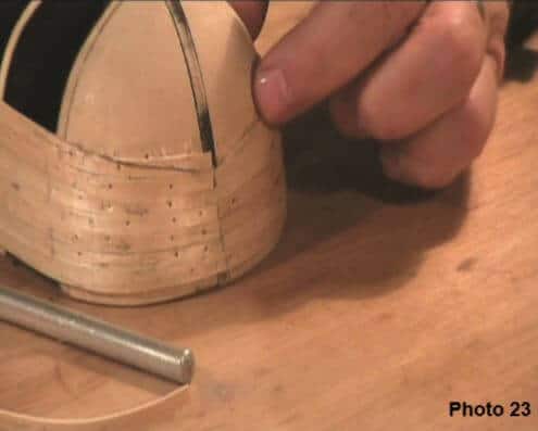
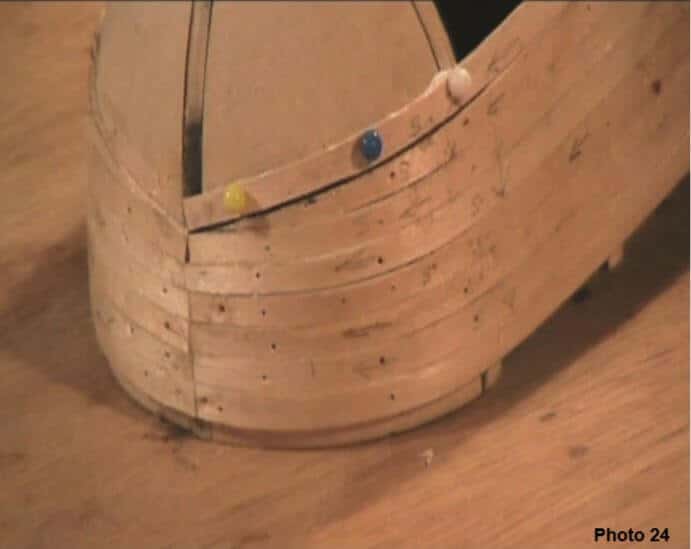
The next step is fit & fix the garboard plank. This plank is the plank that is fitted adjacent to the keel— Photo 25.
Place a plank along the keel and notice at the bow you will have to trim the edge of the plank that fits against the keel to a sharp point—Photo 25. Do not glue the garboard plank in place yet.

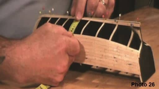
Next use your tape measure and take some measurements between the garboard plank and the last plank fitted from the mid-ship bulkhead frames to the bow. We want to create the same distance across these frames. For the Norfolk this measurement is approximately 40mm—Photo 26.
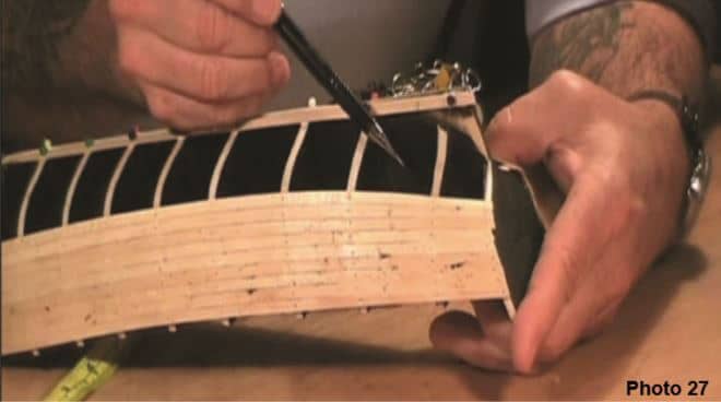
Don’t worry about the distance across the frames at the stern area. As this area will include the deadwood you will need to fit stealers or wedges in later—Photo 27
You will more than likely find the distance at bulkhead frame 1 is slightly less than 40mm. You will need to trim the garboard plank at bulkhead frame 1 to make the distance of the gap along the frames the same—Photo 28
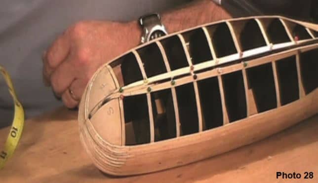
As you progress further down the hull you will find you will need to make further directional changes. The greater the bluff shape of the bow the more directional changes that are required.
Repeat the process described above to achieve each directional change. Do not change the taper on each plank.
Take your time and a well finished hull will be the outcome.
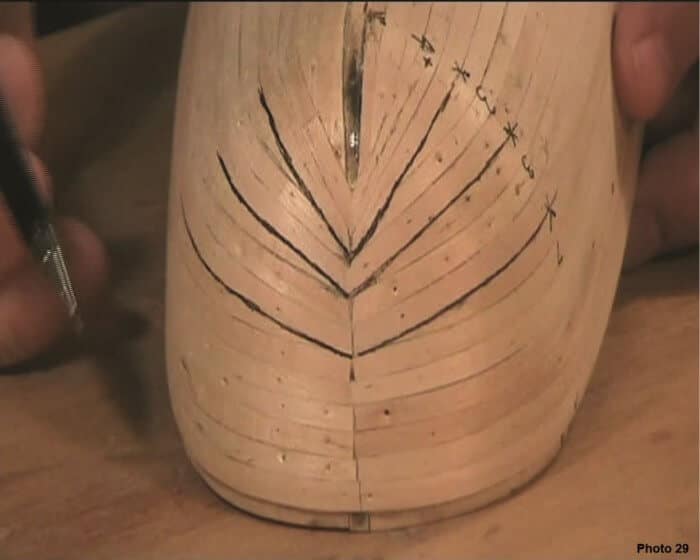
Next we will consider a model that has bulkhead horns to create the bulwark.
5. Models with Bulkhead Frame Horns
Some models have bulkhead frames that rise above the deck level. These are called the bulkhead horns. If your model has bulkhead frame horns you will first need to fit the false deck before starting your planking. Fitting the false deck will add strength to the whole hull.
You will start to plank the hull at or near the deck level. However, once you have finished planking the hull below the deck you will need to plank above the deck line over the horns. You will need to remove the horns later to plank the deck fully so it is important to ensure that as you plank over the horns the planks are not glued to the horns. To ensure this you will need to place sticky tape over the horns. Also, as you plank up the horns make sure you apply glue to the side edge of the planks.
When the whole hull is fully planked you will use a razor saw pushed flush with the false deck to remove the horns. You can then prepare the false deck for planking—this aspect of model ship building is covered in the chapter on Deck Planking.
Photos 30 & 31 show a model that has bulkhead horns.
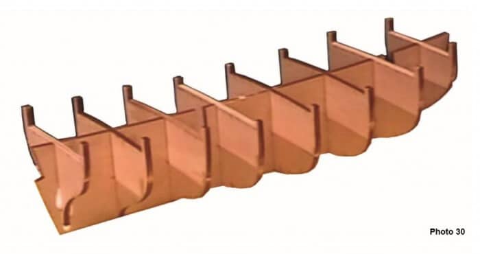
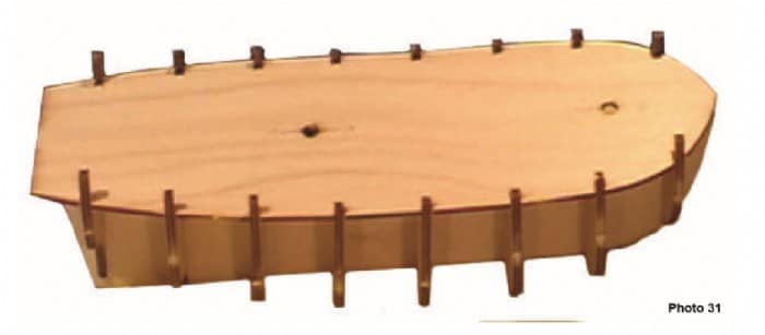
The next steps are to fit the deck (if not already fitted) and the bulwarks.
6. False Deck Fitting
The false deck is the next step if its not already been done. Identify the false deck from the 2mm laser cut plywood. Place it over the bulkhead frames.
Bluff bowed hulls can have some sheer on them—sheer is where the deck surface curves from aft to stern dipping in the central part of the ship. Some ships also had reverse sheer—this is where at the bow the curvature of the deck, after dipping in the middle then curves slightly in the opposite direction. You can see the Norfolk had some reverse sheer at the bow.
If the model you are building has some reverse sheer along the deck it would be wise to use a two part epoxy glue to glue the deck in place. The strains in a deck with reverse sheer could be too much for PVA glue to hold it in place across the bow blocks.
Once the deck is fixed in place use a file to shape the deck edge to align with the bulkhead frames if needed.
7. Bulwarks
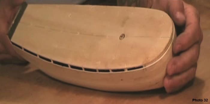
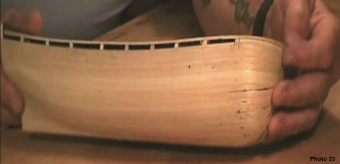
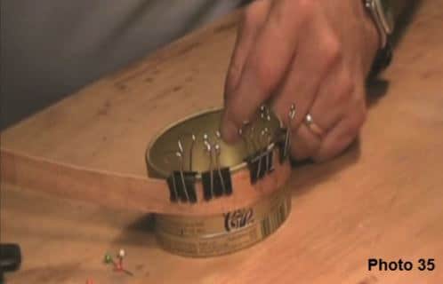
The next step is to fit and fix the bulwarks in place. Identify these parts from the 2mm plywood sheet. Use a hand held plank bender to initially shape the bulkwarks around the bow. Then place both bulwarks in a container of boiling water for approximately 10 minutes. Take them out of the container and clamp them around a curved shape and allow to dry over night.
Once the bulwarks are completely dry fit and fix them in place then sand to form into the hull shape.


8. Second Layer of Planking
In this topic, we will focus on completing the second layer of planking. The process of completing the second layer of planking is essentially the same as for the first layer of planking but with the added advantage of having a solid foundation on which to work.
The second layer of planking is a decorative timber such as walnut, tanganika, teak or mahogany. The thickness will vary according to the size of model you are building. Usually though the second layer of planking is either 0.5mm, 0.6mm or 1mm thick. The width will usually be 5mm or 6mm.
First Planks The first few planks of the second layer to be fitted are over the bulwark and some way down the hull. These planks will not be tapered. For the Norfolk the first six planks can be fitted and glued in position without any tapering. As the planks are a veneer use a contact glue.
As you progress with your planking down the hull continually check the measurements between the bottom of the last plank fitted and the keel at a few points along the hull. These points would be the midship area, the bow area and the stern area.
As you start to see some reduction in the measurement at the bow area you will need to start tapering the planks at their bow end from this run of planks.
Use the same process as previously described for the first layer of planking. The only exception will be that as the planks are very thin veneer you will need to bunch 3 or 4 together to taper them.
Apply the contact glue to both surfaces with a brush and allow the surfaces to dry completely. Take care when placing the plank in position as once contact has been made the plank cannot be moved. If a plank is wrongly positioned it will have to be cut and scraped off.
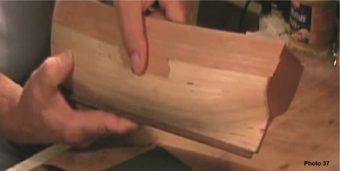
Continue this process until you reach a point where the plank will not lay flat along the line of planks particularly at the bow area—across the bow area the plank will distort and buckle.
This is where you will need to change the direction of the plank. Use the same principle to change the plank direction as previously presented—Photos 2 & 3.
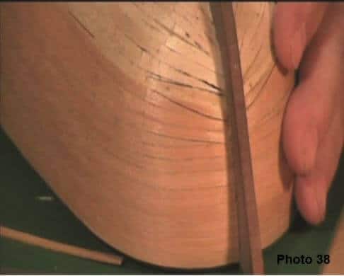
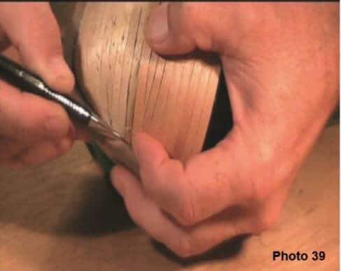
Continue to work down the hull and applying the directional change when required. Continually check the distance between the plank just placed and the keel.
At the stern area you will allow the planks to run along their natural direction. You will need to place stealers or wedges where there are gaps left—Photo 4
Once you have completed the second layer of planking give the whole hull a light sanding and finish with 2 or 3 coats of a clear satin varnish—this will protect the hull from scratches and marks while building the rest of the model—Photo 5.
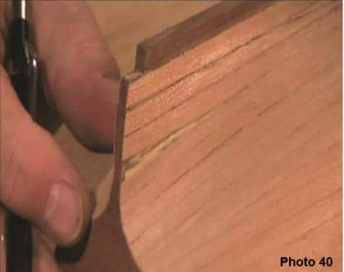
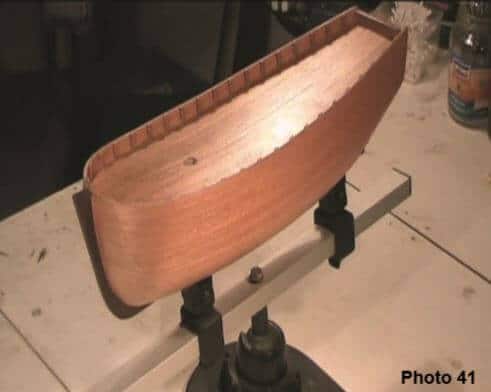
9. Hull Planking—Bluff Bow DVD
View the Hull Planking—Bluff Bow DVD for further tips and techniques.

Learn The Art Of Building A Model Ship
Get started in wooden model ship building today


